
- #Keypad deadbolt how to
- #Keypad deadbolt install
- #Keypad deadbolt software
- #Keypad deadbolt Pc
- #Keypad deadbolt Bluetooth
Install BLEPeripherals (I recommend checking out jeanmatthieud’s branch and installing it in arduino sketchbook folder as it contains some low power GPIOTE stuff which I’ll explain later).SandeepMistry (thanks for this!) did the BLEPeripheral library so that you could use it in Arduino itself.
#Keypad deadbolt software
Usually you have to download the Nordic Software to program these boards, but some people wrote their own stack to program these boards via Arduino. It’s also said to be pretty low powered: ESP8266 takes about 60-200mA while BLE goes down to 0.04mA even while transmitting!
#Keypad deadbolt Bluetooth
It’s like an Arduino but with some proprietary bluetooth stack. To explain briefly, NRF51/NRF52 are a set of programmable BLE boards from Nordic Semiconductors which you can purchase to program GPIO pins on. I am unfortunately a software engineer, with questionable programming skills. The Bluetooth Low Energy(BLE) Programming

YOU CAN ACCIDENTALLY SHORT YOUR CIRCUITS AND CREATE FIRE, SO MAKE SURE ALL CONNECTIONS ARE STRONG. Wiggle the wires around a bit to see that they don’t move. You may need a little more solder than usual to make it stick. For the others, scratch the pins/legs a little, melt some solder on them and then bring a wire close to it and push it down the same.Then bring a wire close to it and push it down on the pads with the soldering iron to fuse them together permanently. For the pads, scratch the pads a little, and melt some solder onto those pads first.You can scrape it off with your fingernails or use a small blade. To solder these parts, you will need to pull off some of the rubbery silicone off the connectors. If your lock looks different, you either trail and error pads/pins or buy another lock. If you want motor control on top of the rest, you need all the pins I’ve listed. If you want to run it off the internal circuit, you need to reach the 3.3V.ħ. Wire in a separate 2 AAA/AA 1.5V batteries via a hole.ģ Pins. In total you have 2/3/7 pins you would be interested in.Ģ Pins. 3.3V: Its next to the MOTOR2 pin and has no testpad.HALL: Which runs 3.3V when locked and 0V when unlocked.The 2 battery connections are exposed (6V +/-).The 2 motor pins are somewhat exposed (4.5V +/-).Here you can see a few things you have access to: Lets investigate the back of the lock, to see which pads/pin can be tapped into. Once you are in that state of mind and have all the materials ready, here are the steps 4 Screw terminals (For disconnecting ease)

2 330Ohm Resistors (If you want motor control from a sketchy H-Bridge circuit)Į. 4 2N2222A331 (If you want motor control from a sketchy H-Bridge circuit)ĭ. 1 470Ohm Resistor (To fix the issue with NRF51 pulling too much current)Ĭ.
#Keypad deadbolt Pc
#Keypad deadbolt how to
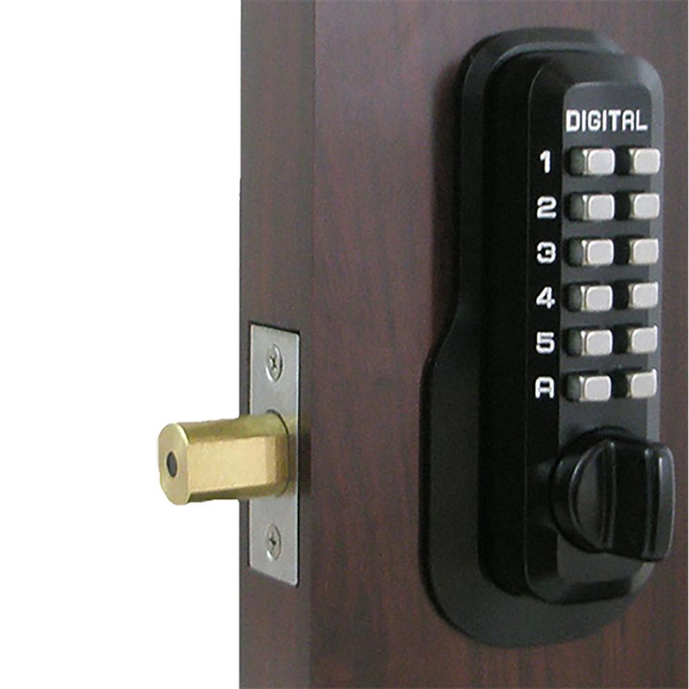
Here’s how to automate your deadbolt lock. I AM NOT RESPONSIBLE FOR ANYTHING YOU DO OR THAT HAPPENS TO YOU This first post of mine is dedicated to you lovely people about automating your doorlock :).īefore we continue, I want you to know thatĪ - you realize off the bat that this is a horrible ideaī - your house’s security can be compromised by some guy with a phoneĮ - the soldering part is hard and I’d admit that this can be artistic soldering at timesį - you could already buy $150 door locks that are more secure than this and have IOT I’ve been a lurker here since I installed home assistant for my own home a year ago and wanted to find some way to give back to the community.


 0 kommentar(er)
